RS-485 Usage
The RS-485 transceiver on the RS485 CAN HAT (SP3485) connects to the Pi’s UART and supports half-duplex communication at up to 10 Mbps. By default, the board ships with hardware auto TX/RX switching, so you can send and receive without toggling any GPIO pins in software.
Prerequisites
Section titled “Prerequisites”-
Enable UART. In
/boot/config.txt(or/boot/firmware/config.txt), make sure the UART overlay is enabled:enable_uart=1 -
Disable the serial console. The Pi’s default login shell on the serial port will interfere with RS-485 data. Use
raspi-configto disable it:Terminal window sudo raspi-configNavigate to Interface Options > Serial Port. Answer No to “login shell accessible over serial” and Yes to “serial port hardware enabled.”
-
Reboot.
Terminal window sudo reboot
Wiring
Section titled “Wiring”RS-485 uses a differential pair. Connect your two devices as follows:
| HAT Terminal | Remote Device |
|---|---|
| A | A |
| B | B |
| GND | GND (recommended) |
Connecting GND between devices is not strictly required by the RS-485 standard, but it is strongly recommended to establish a common reference and prevent ground-potential differences from corrupting data.
Python Example
Section titled “Python Example”Install pyserial and make sure RPi.GPIO is available (it ships with Raspberry Pi OS by default):
pip3 install pyserialimport RPi.GPIO as GPIOimport serial
EN_485 = 4GPIO.setmode(GPIO.BCM)GPIO.setup(EN_485, GPIO.OUT)GPIO.output(EN_485, GPIO.HIGH) # HIGH = transmit mode
t = serial.Serial("/dev/ttyS0", 115200)print(t.portstr)
strInput = input('Enter some words: ')n = t.write(strInput.encode())print(f"Wrote {n} bytes")
# Read back echo (if loopback or remote device echoes)response = t.read(n)print(response)import RPi.GPIO as GPIOimport serial
EN_485 = 4GPIO.setmode(GPIO.BCM)GPIO.setup(EN_485, GPIO.OUT)GPIO.output(EN_485, GPIO.LOW) # LOW = receive mode
ser = serial.Serial("/dev/ttyS0", 115200, timeout=1)
print("Listening on RS-485...")while True: data = ser.readall() if data: print(data)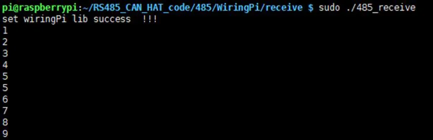
C Example (wiringPi)
Section titled “C Example (wiringPi)”#include <stdio.h>#include <wiringPi.h>#include <wiringSerial.h>
#define EN_485_PIN 7 /* wiringPi pin 7 = BCM GPIO 4 */
int main(void){ int fd;
if (wiringPiSetup() < 0) { fprintf(stderr, "wiringPi setup failed\n"); return 1; }
pinMode(EN_485_PIN, OUTPUT); digitalWrite(EN_485_PIN, HIGH); /* Transmit mode */
fd = serialOpen("/dev/ttyS0", 115200); if (fd < 0) { fprintf(stderr, "Unable to open serial device\n"); return 1; }
serialPuts(fd, "Hello from RS-485!\n"); printf("Data sent.\n");
serialClose(fd); return 0;}#include <stdio.h>#include <wiringPi.h>#include <wiringSerial.h>
#define EN_485_PIN 7 /* wiringPi pin 7 = BCM GPIO 4 */
int main(void){ int fd;
if (wiringPiSetup() < 0) { fprintf(stderr, "wiringPi setup failed\n"); return 1; }
pinMode(EN_485_PIN, OUTPUT); digitalWrite(EN_485_PIN, LOW); /* Receive mode */
fd = serialOpen("/dev/ttyS0", 115200); if (fd < 0) { fprintf(stderr, "Unable to open serial device\n"); return 1; }
printf("Listening on RS-485...\n"); while (1) { if (serialDataAvail(fd)) { char c = serialGetchar(fd); printf("%c", c); fflush(stdout); } }
serialClose(fd); return 0;}Compile with:
gcc -o rs485_send rs485_send.c -lwiringPigcc -o rs485_recv rs485_recv.c -lwiringPiHardware Auto TX/RX Switching
Section titled “Hardware Auto TX/RX Switching”In its default factory configuration, the RS485 CAN HAT provides automatic transmit/receive switching. The RSE (RS-485 Enable) pin is connected through a circuit that detects UART activity and toggles the SP3485 direction pin automatically. This means:
- You do not need to control GPIO 4 in software.
- The transceiver switches to transmit when the UART sends data and returns to receive when the line goes idle.
This is the simplest mode of operation and works well for most applications.
Manual TX/RX Control
Section titled “Manual TX/RX Control”If your application requires explicit control over transmit/receive timing (for example, to implement a custom protocol with tight turnaround requirements), you can switch to manual control:
-
Modify the board. Move the 0-ohm resistor from the “AUTO” position to the “MANUAL” position on the RSE selector pads. Refer to the board silkscreen for pad locations.
-
Control GPIO 4 (BCM) in software. The RSE pin directly drives the SP3485 enable lines:
- HIGH = transmit mode (driver enabled, receiver disabled)
- LOW = receive mode (driver disabled, receiver enabled)
-
Toggle before send/receive.
import RPi.GPIO as GPIOEN_485 = 4GPIO.setmode(GPIO.BCM)GPIO.setup(EN_485, GPIO.OUT)# To transmit:GPIO.output(EN_485, GPIO.HIGH)# ... write to serial ...# To receive:GPIO.output(EN_485, GPIO.LOW)# ... read from serial ...