CAN Bus Circuit
The CAN bus subsystem on the RS485 CAN HAT consists of two ICs in a controller-transceiver architecture. The Raspberry Pi communicates with the MCP2515 controller over SPI, the MCP2515 handles all CAN protocol logic, and the SN65HVD230 transceiver translates between the controller’s logic-level signals and the differential voltages on the physical CAN bus.
The signal flow, from the Pi to the bus, is:
Pi SPI → MCP2515 (protocol framing, arbitration, filtering) → SN65HVD230 (logic-to-differential conversion) → CAN bus (H / L)
MCP2515 — CAN Protocol Controller
Section titled “MCP2515 — CAN Protocol Controller”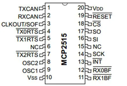
The MCP2515 is a standalone CAN controller from Microchip that implements the full CAN V2.0B specification. The Raspberry Pi has no native CAN peripheral, so the MCP2515 provides that capability entirely through the SPI bus.
SPI Connection to the Pi
Section titled “SPI Connection to the Pi”The MCP2515 occupies SPI bus 0, chip select 0 on the Raspberry Pi:
| MCP2515 Pin | Pi GPIO | Function |
|---|---|---|
| SCK | GPIO 11 (SPI0_SCLK) | SPI clock |
| SI | GPIO 10 (SPI0_MOSI) | SPI data in (from Pi) |
| SO | GPIO 9 (SPI0_MISO) | SPI data out (to Pi) |
| CS | GPIO 8 (SPI0_CE0) | Chip select (active low) |
| INT | GPIO 25 | Interrupt output (active low) |
The interrupt pin on GPIO 25 allows the MCP2515 to signal the Pi when frames arrive, errors occur, or transmit buffers become available. This avoids the need for the Pi to continuously poll the controller over SPI.
CAN Protocol Features
Section titled “CAN Protocol Features”The MCP2515 handles all CAN bus protocol details in hardware:
- Standard (11-bit) and extended (29-bit) data frames — both identifier formats are supported for transmission and reception.
- Remote frames — the controller can send and respond to remote transmission requests.
- Message filtering — two acceptance mask registers and six acceptance filter registers allow the controller to discard unwanted frames in hardware before they ever reach the Pi. This reduces SPI traffic and CPU load significantly on busy networks.
- Three transmit buffers — frames can be queued with priority levels so that higher-priority messages are sent first.
- Two receive buffers — incoming frames are double-buffered to prevent overrun when the Pi cannot service interrupts immediately.
Clock Source
Section titled “Clock Source”The MCP2515 requires an external crystal oscillator to derive its internal timing. This clock frequency is critical for CAN bit timing calculations.
SN65HVD230 — CAN Transceiver
Section titled “SN65HVD230 — CAN Transceiver”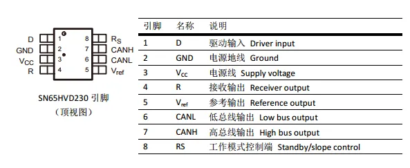
The SN65HVD230 is a 3.3V CAN transceiver from Texas Instruments. It sits between the MCP2515’s logic-level TX and RX pins and the physical CAN bus differential pair.
Signal Connections
Section titled “Signal Connections”| SN65HVD230 Pin | Connected To | Direction | Function |
|---|---|---|---|
| D (Data In) | MCP2515 TXCAN | Input | Transmit data from controller |
| R (Data Out) | MCP2515 RXCAN | Output | Received data to controller |
| CANH | Terminal H | Bus | CAN bus high line |
| CANL | Terminal L | Bus | CAN bus low line |
| Rs | Bias network | Config | Mode select |
During transmission, the MCP2515 drives the D pin with the serialized CAN frame. The SN65HVD230 converts this single-ended signal into differential voltages on CANH and CANL. During reception, the transceiver samples the differential voltage between CANH and CANL and outputs the recovered digital signal on the R pin back to the MCP2515.
Operating Modes
Section titled “Operating Modes”The SN65HVD230 supports three operating modes, selected by the voltage on its Rs (slope control) pin:
- High-speed mode (Rs tied to ground) — maximum slew rate for highest bus speeds. This is the typical configuration for CAN networks running at 500 kbps or 1 Mbps.
- Slope control mode (resistor on Rs) — reduces electromagnetic emissions by slowing the signal edges. Useful in environments with strict EMI requirements, at the cost of maximum achievable bus speed.
- Standby mode (Rs tied to VCC) — the transmitter is disabled and the receiver operates at reduced current. The transceiver can still detect bus activity to wake the system.
Bus Termination
Section titled “Bus Termination”A CAN bus requires 120-ohm termination resistors at each physical end of the bus to prevent signal reflections. The RS485 CAN HAT does not include an onboard termination resistor. If this board is at one end of your CAN bus, you must add a 120-ohm resistor between the H and L terminals externally.
Putting It Together
Section titled “Putting It Together”When a CAN frame is transmitted:
- The Pi writes frame data to the MCP2515 over SPI (ID, data length, payload, and priority).
- The MCP2515 waits for bus idle, performs arbitration, and serializes the frame onto its TX pin according to the CAN protocol.
- The SN65HVD230 converts each bit into differential bus voltages — dominant (CANH driven high, CANL driven low) or recessive (both lines floating to mid-level).
- The differential signal propagates along the bus wiring to other nodes.
When a CAN frame is received:
- The SN65HVD230 detects the differential voltage on CANH/CANL and outputs the recovered bit stream on its R pin.
- The MCP2515 deserializes the frame, checks the CRC, and runs the identifier through its acceptance filters.
- If the frame passes filtering, the MCP2515 stores it in a receive buffer and asserts the interrupt pin (GPIO 25).
- The Pi reads the frame data from the MCP2515 over SPI in response to the interrupt.