RS-485 Circuit
The RS-485 subsystem on the RS485 CAN HAT uses a single IC — the SP3485 half-duplex transceiver — paired with a transistor-based automatic direction control circuit. This combination allows the Raspberry Pi to communicate over RS-485 using its UART pins without any software-managed direction switching.
SP3485 — RS-485 Transceiver
Section titled “SP3485 — RS-485 Transceiver”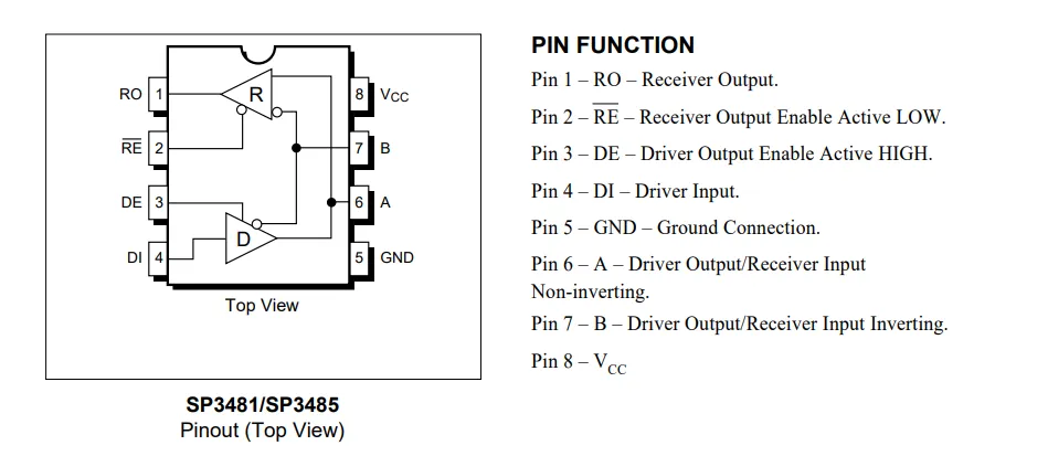
The SP3485 is a low-power, half-duplex RS-485 transceiver operating at 3.3V. “Half-duplex” means the chip can either transmit or receive at any given moment, but not both simultaneously. The A and B differential lines serve double duty — carrying data in both directions, with direction controlled by the enable pins.
Pin Connections
Section titled “Pin Connections”| SP3485 Pin | Connected To | Direction | Function |
|---|---|---|---|
| RO (Receiver Output) | Pi RXD | Output | Received data to Pi |
| DI (Driver Input) | Pi TXD | Input | Transmit data from Pi |
| RE̅ (Receiver Enable) | Control circuit | Input | Active LOW — enables receiver |
| DE (Driver Enable) | Control circuit | Input | Active HIGH — enables driver |
| A | Terminal A | Bus | Non-inverting differential line |
| B | Terminal B | Bus | Inverting differential line |
RE̅ and DE are complementary in normal operation: when the driver is enabled (DE HIGH), the receiver is disabled (RE̅ HIGH), and vice versa. On this board, both pins are driven by the same control signal, so the chip is always in either transmit or receive mode — never both, never neither.
Differential Signaling
Section titled “Differential Signaling”RS-485 encodes data as the voltage difference between the A and B lines:
| Condition | Interpretation |
|---|---|
| V(A) - V(B) > +200 mV | Logic 1 (mark) |
| V(A) - V(B) < -200 mV | Logic 0 (space) |
This differential scheme gives RS-485 its noise immunity. Common-mode noise — interference that shifts both A and B by the same amount — is rejected because only the difference matters. This is why RS-485 can reliably span hundreds of meters where single-ended UART signals would fail.
Bus Termination
Section titled “Bus Termination”A 100-ohm termination resistor is present on the board between the A and B lines. This resistor absorbs signal reflections at the end of the cable and prevents ringing that could cause bit errors.
Line Protection
Section titled “Line Protection”A TVS (Transient Voltage Suppressor) diode on the A and B lines clamps voltage spikes before they reach the SP3485. This protects against surges from lightning strikes, ESD events, and inductive load switching — all common in industrial environments where RS-485 is deployed. The TVS response time is in nanoseconds, fast enough to suppress transients that would otherwise destroy the transceiver.
Automatic TX/RX Control
Section titled “Automatic TX/RX Control”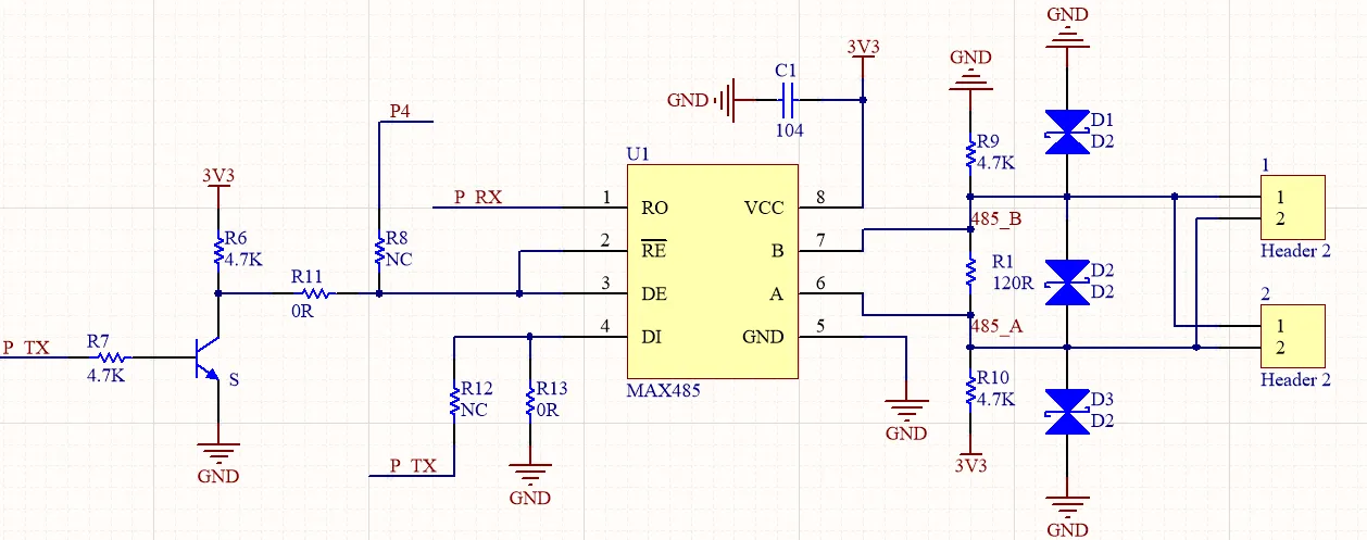
By default, the board ships with automatic direction control enabled. A small transistor circuit monitors the Pi’s UART transmit line (P_TX) and switches the SP3485 between receive and transmit modes without any GPIO involvement.
How It Works
Section titled “How It Works”The circuit operates on a simple principle: the UART TX line idles HIGH when no data is being sent.
Receiving data (idle state):
When P_TX is idle (HIGH), the transistor conducts. This pulls the control line to a state where RE̅ goes LOW, enabling the SP3485 receiver. Data arriving on the A/B differential pair is converted by the SP3485 and output on the RO pin, which feeds the Pi’s RXD. The Pi reads incoming bytes through its UART as normal.
Transmitting data:
When the Pi begins transmitting, P_TX drops LOW for the start bit. This causes the transistor to cut off, which drives DE HIGH and RE̅ HIGH — enabling the transmitter and disabling the receiver. The SP3485 now drives the A and B lines based on the data on its DI pin (connected to P_TX).
During the body of the transmitted byte, when a logic ‘1’ bit is sent, P_TX goes HIGH momentarily. The transistor briefly conducts, which would normally re-enable the receiver. However, during this brief window the SP3485 enters a high-impedance state on the bus side, and the bit duration is short enough that no corruption occurs. The chip returns to active transmit mode as soon as the next LOW bit (or stop/start bit) arrives.
Timing Implications
Section titled “Timing Implications”After the last byte is transmitted, P_TX returns to idle HIGH. The transistor conducts again, switching the SP3485 back to receive mode. There is a brief dead time during this transition where the chip is neither fully transmitting nor fully receiving. For most RS-485 applications at standard baud rates (9600, 19200, 38400, 57600, 115200), this dead time is negligible and causes no issues.
Manual TX/RX Control
Section titled “Manual TX/RX Control”For applications that require precise direction control or very high baud rates, the board can be reconfigured for manual (software-controlled) direction switching.
Hardware Modification
Section titled “Hardware Modification”Switching to manual control requires physically moving a 0-ohm resistor on the board. The board has two resistor positions — one for automatic mode (factory default) and one for manual mode. Moving the resistor disconnects the transistor circuit and connects the SP3485 enable pins to the RSE control line instead.
Software Direction Control
Section titled “Software Direction Control”With manual mode enabled, the RSE pin — routed to GPIO 4 on the Raspberry Pi — controls the SP3485 direction:
| GPIO 4 State | SP3485 Mode | DE | RE̅ |
|---|---|---|---|
| HIGH | Transmit | HIGH | HIGH |
| LOW | Receive | LOW | LOW |
The software must manage the timing explicitly:
- Set GPIO 4 HIGH before writing data to the UART.
- Transmit the data.
- Wait for the UART transmit buffer to fully drain (all bytes shifted out on the wire).
- Set GPIO 4 LOW to return to receive mode.
When to Use Manual Control
Section titled “When to Use Manual Control”Manual control is preferable in these situations:
- High baud rates (above 115200) where the automatic switching circuit’s transistor delay causes bit errors.
- Multi-drop networks where precise turnaround timing is required by the protocol (e.g., Modbus RTU with strict inter-frame timing).
- Low-power applications where you want to keep the transceiver in a known state (receiver disabled) to save power during idle periods.
- Deterministic timing requirements where the automatic circuit’s variable switching behavior is unacceptable.